The ZEBRA:
The Electrical System
38-year-old truck, 38-year-old wires. So I gutted the truck of all wires and electrical components and started over again, in 12 volt.
Please, no 12/24-volt wars. I had a 12-volt starter, and a 12-volt alternator. I went with a 12-volt system.
Although I've wired up dashes and other components in the past with several other cars I've owned, never before had I done a COMPLETE system. Someone suggested a book to me so I got it and read it, several times, and followed it word for word. Jim Horner ISBN 0-89586-238-7 calls that book Automotive Electrical Handbook. It was very helpful. With it I was able to plan, design, engineer, fabricate, test and install a wiring harness for the ZEBRA. Here's a summary of about two months worth of work.
First I decided what I wanted and how I wanted it to work. Then drew up wiring diagrams for each component or system. Installed all the electrical draws in their proper location. Connected them with string and rope and flagged all branch points. Placed the rope on the floor and started to lay down the wiring - 30+ rolls of the stuff. Wrapped it with loom tape. Installed it on the truck. Tested the harness. Terminated all the wires.
Tested all the components. And Voila... nervous system intact. No fires!
Some of the details are as follows:
- every wire size was gauged one size larger than required for the amperage draw in case I wanted to add other items to that circuit at a later time.
- color-coded insulated wires used. When I ran out of color choices, wires were then traced using indelible ink along the whole length of the wire to aid in diagnosis and location later. This prevented me from needing to replicate wire colors adding to confusion.
- all in-harness splices or branch points were soldered and shrink-wrapped.
- fuse panel is GM-ISO style giving me the option of breakers for circuits I felt better suited to breaker protection.
- total of 18 ignition circuits and 12 battery circuits used.
- trailer connectors used for bulkhead locations for water resistance and ease of disconnection.
- Backup, spots, fog and headlights wired using relays for maximum light output.
- provision in the harness for CB, Radio, Amp, and CD changer. :-0
- fuse panel relocated from stock under hood location to body panel behind left rear seat inside the cab to keep this vital component clean and dry.
- A used glow plug relay from a car was installed with a dash indicator light, as a car would have.
- electric cut-off solenoid used for the injector pump idle so the truck turns off like a car would.
- Ground cut-off switch for safety and security.
- Huge 2/0 welding cable was used to hook up the winches
Other items of note, or interest:
- Two dry cell Platinum batteries with a Painless 200 amp battery isolator.
- 190 Amp 12V alternator should keep those batteries from draining.
- On board Premier Power Welder for trail repairs requiring welding and 110 outlet for grinding or other such duties.
- Extreme Aire 100% duty 150psi on board compressor.
- VDO white face gauges - 9 in all.
- backup lights switched at the shifter, dash, or rear bumper.
- swivel mounted side flood lights switched at the dash or at the light for nighttime trail travel, trail repairs, or setting up camp
- steering column mounted signal light and hazard light switch JCW art No. 81-1093W.
- all dash and exterior toggle switches rubber booted for water resistance.
- back-up alarm switched at the shifter because this truck is a crowd magnet, and switched at the dash because I don't want to hear it on the trail.
-3-12V power outlets for accessories -as yet to be determined.
- a VDO programmable speedo was used in conjunction with a "Hall effect sensor" - this was adapted to the transmission speedo cable hook-up and works great. I get super accurate speed readings even when changing tire sizes! See Ron's web page for a tech article on this.
- a VDO whiteface tachometer is used (even though several people said it was not compatible) and hooked into the alternator as a pickup. Works fine. It is tunable, and was done so given a 750 rpm idle speed.
- Hella crystal headlight lenses with high intensity halogen bulbs used for headlights.
- GM style H/L switch with dimmable dash lighting.
So far this system is functioning very well. I haven't popped a fuse or breaker yet so the loads were properly calculated. Some minor bugs do exist however:
*I used one dash indicator light to show both the backup and side spotlights being on. Double pole switches were used. But I'm getting feedback somewhere since they all come on at once. I'll have to sit down with the wiring diagram to figure it out.
*The dash indicator charge light stays on even though the alternator is charging the batteries - itís supposed to turn off.
*I wanted the headlights to be switched by the ignition so that I couldn't leave them on. They turn off, but the parking lights stay on.
*The clock was ground before the ground cut-off switch so that it will always read good time. But the clock does not function if the ignition is off, and the cut-off switch is on, and works if the cut-off switch is off. More time with the wiring diagram here too.
*I re-used the Unimog dimmer switch and it seems to stick. I'll have to service or replace it.
*Every once in a while the glow plugs won't come on with the key, but a quick rap on the panel where the relay is located will get them to come on. The only two used components of the electrical system are showing their age!
As careful as I was when fabricating the wiring harness, I missed three wires. To make it worse, I only noticed it after I had installed the harness and was hooking up the fuse panel. It took four hours to install these three wires in a way that it looked intentional.
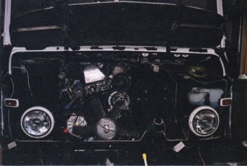
Not a great shot, but notice all the string and rope used for planning the electrical harness route.
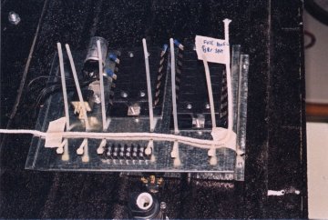
Fuse panel mounted on the inside left rear body panel.
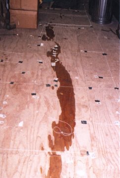
String and rope then taped to the floor.
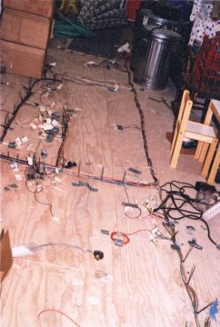
Rolls and rolls of wire placed along the rope.
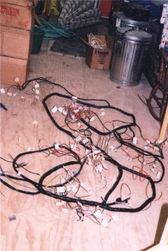
Wrapped with harness tape and ready to install!
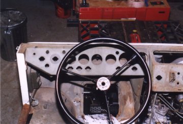
Before shot of the dash.
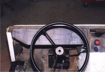
New blank dash panel.
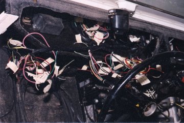
Harness in place, ready for termination.
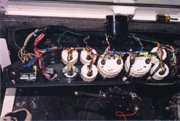
Terminated dash panel.
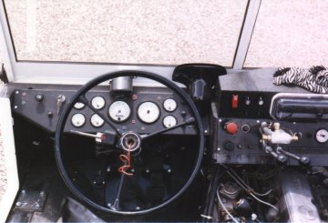
After shot of the dash - note the VDO whiteface gauges, 12v JCW w/w motor, JCW column mounted signal lever, and on the center of the dash (with Zebra mascot) - parklock, steering brakes, and the future location of a radio in a waterproof pod.
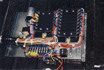
Terminated fuse panel.
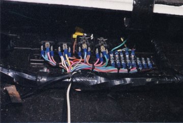
Headlight relays and terminal block located under the hood.
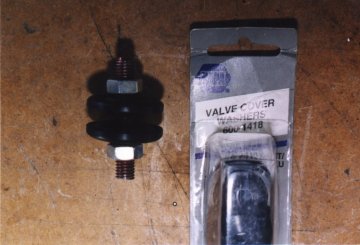
Home-made bulkhead connectors.
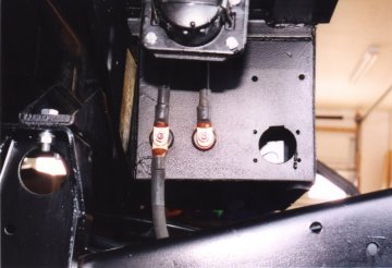
Bulkhead connectors mounted in the battery box. Wires go to the winches, and remote boosting jack. Note the rubber stopper in the left rear portion of the battery box for ability to drain.
The Electrical system - Update 2006
The 200 amp alternator I used had a double V pulley on it which was spaced wider
than the spacing of the crank shaft pulley. Standard GM spacing, not MB spacing.
This, over time wore out the belt that was running on a slight angle. I noticed
this after driving out of Prichett Canyon in Moab. The belt broke and also threw
the P/S belt off of its pulley. I left the one belt on the alt. and replaced the
P/S belt with my spare and continued on - for about one mile. Then the other belt
broke. The first break must have damaged the second belt as well. Oh well, I carry
spares for that reason and it was quickly replaced. But the problem remained. So I
took both pulleys down to the local machine shop (he knows me well now) and had a
new double V pulley machined for the alternator. That should no longer pose a problem.
I've replenished my spares in case. Learn from this - always carry spare belts. I
prevented myself from getting bitten by doing so. Most of those in my group were
surprised that I had some. I guess they don't carry them for their rigs.
Next: The Flatbed
-
|
