The ZEBRA:
Part 2 - The Frame
Last week I discussed the original condition of the Zebra and left off at the end of tearing it down to the frame. Several times during the tear down a pressure washer was used to de-crud components before removing them from the frame. Even though, much more de-crudding was needed before painting and rebuilding could begin. A lot of work!
The frame and many other components were sandblasted free of dirt, grime, old paint and rust. Then given one coat of POR-15 rust paint, and one coat of POR-15 chassis coat black. If a component did not lend itself well to sandblasting, it was cleaned, degreased, stripped of paint using chemicals and then given the same coats of POR-15 paint.
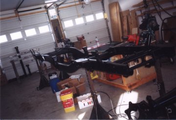
The bare frame after two coats of POR-15.
Way back someone had mentioned an old trick of using one can of crystal Draino with 5 gallons of water to use as a paint stripper. I kept that in the memory banks, and when time came I tested it out. It worked so well I decided to go high volume. A 30-gallon plastic garbage can with 5 Draino's and 25 gallons of water was used over and over again, even one year after initial mixture with much success. Even doors were stripped this way! Thanks to whoever taught me that trick.
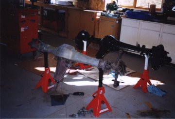
The rear axle POR-15'd, front axle stripped of paint and waiting for new seals.
Once the components were starting to go back onto the frame I saw the need for the first modification. There is just too much frame hanging out behind the rear axle. Departure angle could be significantly increased with discriminate use of a Sawzall. This was also a good location for a rear-mounted winch. A Pierce 12,500 lb, 12-volt winch with an 11 inch drum measures 26 inches in width. The frame rails are 26-1/2 inches apart. Sounds like a plan. So, the rear most frame crossmember and diagonal brace were removed, the brace discarded, and the crossmember reworked and relocated forward in the frame about 15 inches.
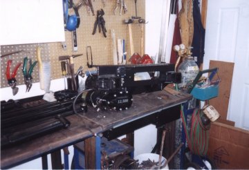
Winch and re-worked rear frame x-member. Note the two 2-inch receivers.
That crossmember was thickened up with the addition of 1/4-inch plate (now total of 1/2-inch thick), and modified to incorporate a winch mount, roller fairlead, 2 - 2" receivers, a 7-pin trailer connector and the 4-pin winch control connector. The two receivers are for their versatility: interchangeable clevis hooks, towing accessories, bike mounts, etc. Looks all business back there.
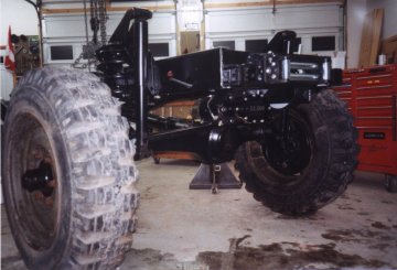
The winch in place. Note the shortened frame rails.
The winch was mounted as low as possible for C.G. reasons, and mounted using a three point system. Any flex which could occur between the last two cross members is not inhibited by winch mounting, nor can flex occur through the winch casing itself and bind the gears or crack the case. Mounting the winch this low provided more clearance between the frame rails, the fit was not as tight as I had originally calculated. Spooling the winch from the top of the drum allowed me to drop it such that the winch motor is below the frame rail leaving plenty of room. A skid plate will have to be fabricated later as it is now a potential vulnerability.
After mounting the winch I was able to determine where to cut off the frame rails. Turns out a full 15" (OK, 35cm) was removed. This took out the rear cargo bed mounting brackets. No problem. A custom bed to come. Angle of departure was increased from 45 to 75 degrees!
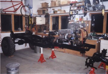
Starting to come together. Front end is still waiting for seals.
For trail prowess, I wanted nothing mounted outside of the frame rails between the front and rear tires. This meant relocating batteries, fuel tanks, and spare tire. With all this out of the way, more trail obstacles could be managed without worry for damage, however, it was a real chore to relocate these and try to maintain a low center of gravity. These items to be addressed later.
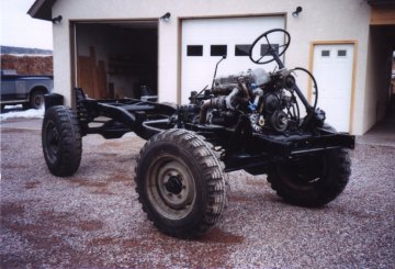
Rolling chassis. Notice how the power steering pump was not mounted on the horizontal plane - mistake.
Skid plates remain to be constructed. So far, I see the need for a front skid plate integrated with a bumper/winch mount, a transmission skid plate, and as mentioned before, another for the rear winch, which seems a little vulnerable to rock damage on extreme departures.
It was nice to see that a lot of modifications being performed on other trail rigs had already been addressed by Mercedes: boxed frame rails forward of the transmission for strength, shaved and thickened differential housings for increased clearance, protection, and less chance of hooking up on a rock, and extra heavy-duty everything.
How's it work? About the only thing here to report is that I don't think the Pierce winch is up to snuff with its pulling power. My only test of it so far was a straight single line pull, first wrap of the drum, unloaded truck on hard ground (no mud), with about a 15' hill and it was hurtin' to pull. It's wired with 2/0 welding cable so no resistance there and there is plenty of amperage with dual batteries and 190-amp alternator. Wait, come to
think of it, the alternator bracket broke on this incident so there was no charging during the pull. But, the batteries were fully charged dry cell Platinums hooked up in parallel. Next summer I'll run more tests on it and give a full report. I wouldn't run out and buy one yet if you're thinking about it for your own truck.
The Frame - Update 2006
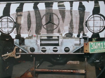
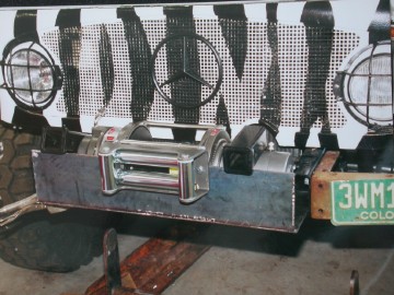
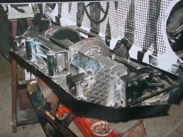
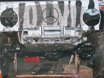
One new thing here is the installation of a front mounted Warn M12000 12Volt winch.
My original intention was to have a front mounted hydraulic winch, but then after
speaking with others and thinking about things, I decided to go electric so it can
be used without the engine running -which would be good in an upside down situation.
I chose to mount it low between the frame rails rather than above them which cost me
some approach angle, but there is less obstruction to airflow in front of the grill.
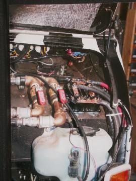
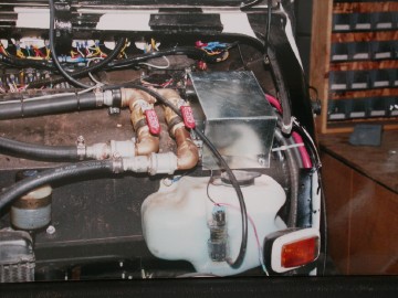
I also relocated the solenoid box from where it came, on the top of the winch, to
under the hood, drivers side. The remote handheld control now plugs into the side
of the fender in front of the drivers door. Also, remember the 2 receivers on either
side of the rear winch, and again on the rear of the flatbed? Well I've got another
pair on the front bumper, so now, anything I make for one location can be moved to
the others, and I have a selection of 2 receiver recovery hooks and clevis that swap
back and forth depending on need. In the plans are a pair of Rock Wheels which can
slide into the front receivers for real crazy stuff - which I have seen the need for already!
These pictures show the front winch mount fabrication, and new location for the
solenoids. You can just see the plug receptacle for the hand held on the side of the fender.
Winch.mount.2.jpg
Winch.mount.1.jpg
Winch.mount.7.jpg
marioWinch.mount.6.jpg
Winch.solenoids.jpg
Winch.solenoid.cover.jpg
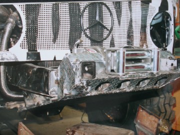
Winch.mount.8.jpg
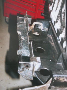
Winch.mount.5.jpg
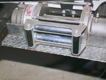
Winch.mount.4.jpg
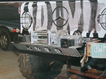
Winch.mount.3.jpg
The rear Pierce winch blows. It does not pull its rated capacity, and I've seized
one of the solenoids. It is now a last resort item, and will be replaced with
another Warn product. I just hope that I can salvage some of the rear winch mount.
Another new item, which may be of interest to some of you is a belly/tranny skid
plate. I have the 2 speed crawler box added to the trans and wanted it protected.
I thought about running some tubes underneath and plating that but felt it would
cost too much in clearance. I finally decided on a U shaped frame using 2x1/4
angle steel and mounted to the frame rails. This then supports a 3/4 inch thick
piece of nylon board. The board is slippery and so glides over obstacles and is
lightweight. If enough deflection occurs it tops out on the transmission and is
therefore supported. I bought my nylon white, but should have gotten the available
black color - oh well.>
picture shows skid plate with temporary plywood pattern - I'll try to update this for you.
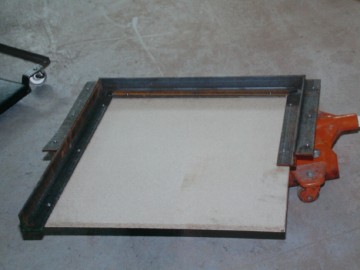
Trans.skidplate.jpg
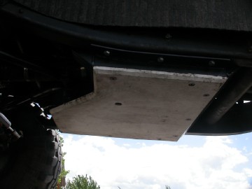
skidplateinstalled2.jpg
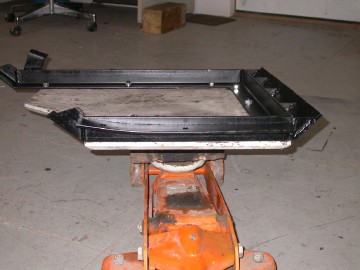
skidplatedone.jpg
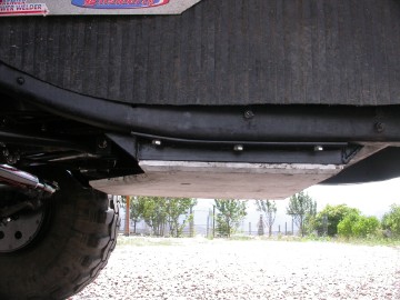
skidplateinstalled.jpg
Next - Engine and transmission
-
|
